
Introduction
Zigbee is not a simple wireless protocol. It is a complete mesh networking ecosystem built atop IEEE 802.15.4 physical and MAC layers, designed to solve the fundamental problem of low-power, multi-hop wireless communication in constrained environments. Where WiFi and cellular assume reliable backhaul and plentiful power, Zigbee assumes neither. It trades bandwidth for range, latency for energy efficiency, and centralized coordination for distributed mesh self-healing.
Understanding Zigbee requires understanding its layers: the physics of 2.4 GHz direct-sequence spread spectrum, the framing discipline of CSMA/CA medium access, the on-demand routing algorithms that build paths dynamically, the cryptographic protections that prevent unauthorized network membership, and the semantic abstraction of the Zigbee Cluster Library that lets heterogeneous devices speak a common language.
This article dissects each layer from first principles. We’ll examine the IEEE 802.15.4 physical layer, trace frame flow through five protocol stack layers, dissect the Ad-Hoc On-Demand Distance-Vector (AODV) routing algorithm that powers mesh self-healing, explore device roles (coordinator, router, end device), detail the Zigbee 3.0 Cluster Library that enables interoperability, and examine practical security bootstrapping with install codes, link keys, and Green Power for energy harvesting devices. We’ll also clarify Zigbee’s role as a transport layer beneath the Matter application protocol, and discuss deployment patterns for smart home and industrial sensing systems.
The IEEE 802.15.4 Physical Foundation
Frequency, Modulation, and Channel Plan
Zigbee operates in the 2.4 GHz Industrial, Scientific, Medical (ISM) band—the same unlicensed spectrum shared by WiFi, Bluetooth, and hundreds of consumer and industrial devices. This is both strength and vulnerability: no license required, but interference is always present.
Physical layer parameters:
– Frequency: 2405 MHz to 2480 MHz
– Channels: 16 channels (11–26), 2 MHz wide, spaced 5 MHz apart. Channels 12–15 overlap with WiFi; channels 15–26 fall between WiFi 40 MHz wide channels
– Modulation: Direct Sequence Spread Spectrum (DSSS) with Offset-QPSK on 2-Mbps chip rate
– Data Rate: 250 kbps (the spread spectrum divides 2 Mbps chip rate by 8, yielding 250 kbps payload)
– TX Power: 0 dBm nominal (1 mW), ranging from −32 dBm to +20 dBm depending on hardware capability
Why spread spectrum? The chip rate (2 Mbps) is much higher than the data rate (250 kbps). The signal is spread across a wide frequency band, making it resistant to narrowband interference—a jammer must spread its power across the entire 2 MHz channel to disrupt the signal. A WiFi packet burst (which is several Mbps) will create interference, but Zigbee can often recover because the signal is spread.
Why 250 kbps? It is the sweet spot between range and power consumption. Higher data rates require shorter transmit duty cycle (less time to transmit a fixed payload), lowering range. Zigbee’s 250 kbps allows payloads up to 127 bytes to be transmitted in ~4 ms, leaving the radio off most of the time. A temperature sensor can wake once per minute, transmit in 5 ms, then sleep 59.995 seconds, drawing minimal current.
Range: Typical open-air range is 100–200 meters in line-of-sight. In buildings with walls and interference, expect 10–30 meters per hop. This is why mesh networking is essential: a message too weak to reach the coordinator can be relayed through intermediate routers.
The Five-Layer Stack: From Bits to Application Semantics
Zigbee is a layered protocol. Each layer encapsulates the one below, adding headers and addressing information.
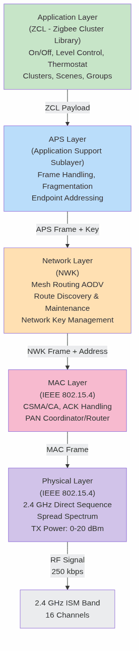
Layer 1: Physical (PHY)
The PHY layer is responsible for:
– Frequency synthesis and tuning to one of 16 channels
– TX modulation: Converting bits to spread-spectrum RF
– RX demodulation and despreading: Recovering bits from RF
– CCA (Clear Channel Assessment): Detecting activity before transmitting (used by MAC layer for CSMA/CA)
– RSSI (Received Signal Strength Indicator): Measuring link quality
The PHY layer outputs 127-byte MAC frames to the MAC layer.
Layer 2: MAC (Medium Access Control)
IEEE 802.15.4 MAC is CSMA/CA with collision avoidance—simpler and lower-overhead than WiFi’s complex rate adaptation and retransmission logic.
MAC frame structure:
[Preamble: 4B] [SFD: 1B] [Length: 1B] [Frame Control: 2B] [DSN: 1B]
[Dest PAN: 2B] [Dest Addr: 2-8B] [Src Addr: 2-8B] [Security Info: ≤21B] [Payload: ≤115B] [FCS: 2B]
Addressing: IEEE 802.15.4 uses two types of addresses:
– Extended (64-bit MAC address): Globally unique, burned into hardware, used during joining and commissioning
– Short (16-bit address): Assigned by the Zigbee Coordinator during network join, used for routing and relaying
A router relaying a frame resets the TTL (time-to-live) and increments the MAC sequence number, allowing the coordinator to detect loops.
CSMA/CA operation:
1. Node has a frame to transmit.
2. Perform CCA: sample the channel; if clear, wait random backoff (0–7 slot periods).
3. Perform CCA again; if still clear, transmit immediately.
4. If not clear, back off and retry (up to 3 attempts for MAC-layer retransmission).
5. If all retries fail, frame is dropped, and upper layers (NWK) detect the failure via absence of ACK.
Key advantage: No pre-negotiation, no association beacons (unlike WiFi), minimal overhead. A device can hear the coordinator’s beacon once per second, learn the PAN ID and network parameters, and join without complex handshakes.
ACK handling: If the recipient receives a valid frame, it sends an immediate ACK (11 bytes, ~0.5 ms). If the sender does not receive ACK within ~1 ms, it retries at MAC layer.
Layer 3: Network (NWK)
The Network layer implements mesh routing and network management. It sits between the MAC layer (single-hop, point-to-point) and the APS layer (semantically meaningful commands).
NWK frame structure:
[Frame Control: 2B] [Dest: 2B] [Src: 2B] [Radius/TTL: 1B] [Seq: 1B] [Src Route Info: Variable] [Payload: ≤90B]
Key responsibilities:
– Mesh routing via AODV: Dynamically discover and maintain multi-hop paths
– Network joining: Authenticate new devices, assign short addresses
– Route caching: Remember recently used paths to avoid repeated route discovery
– Endpoint addressing: The NWK layer adds a 1-byte endpoint ID to reach specific application clusters on a device
Device roles at NWK layer:
– Coordinator (ZC): Network root, always powered, never sleeps. Only one per network. Forms the network by choosing PAN ID and channel. Acts as default hub for route discovery.
– Router (ZR): Extends mesh, always powered, never sleeps (or sleeps infrequently for polling). Can relay frames for other nodes and for end devices. Can join and rejoin the network.
– End Device (ZED): Leaf node, battery or mains powered, can sleep to save energy. Cannot relay frames for other nodes. Must maintain a parent link to a router or coordinator.
Route discovery (AODV algorithm—detailed in next section): When a node has a frame for a destination address not in its routing table, it initiates RREQ (Route Request). Intermediate routers forward the RREQ, and the destination responds with RREP (Route Reply). The reverse path is cached and used for subsequent frames.
Layer 4: APS (Application Support Sublayer)
The APS layer bridges the gap between raw network-layer routing and application-layer semantics. It provides:
- Fragmentation: Splitting large payloads into MAC-layer chunks (≤115 bytes) and reassembling at the receiver
- Reliability: End-to-end retransmission. A frame sent via APS is considered “delivered” only when the destination acknowledges. Retransmissions happen at APS layer, independent of MAC retries.
- Endpoint addressing: Each device can host up to 254 endpoints (virtual devices). Endpoint 0 is reserved for ZDO (Zigbee Device Object) management messages.
- Duplicate filtering: Dropping duplicate frames using sequence numbers, preventing infinite loops in case of weak routing decisions
- Binding: Associating pairs of devices so that a source device can address a destination without knowing its network address (binding table stores the mapping)
APS frame structure:
[Frame Control: 1B] [Dst Endpoint: 1B] [Cluster ID: 2B] [Profile ID: 2B] [Src Endpoint: 1B] [APS Seq: 1B] [Payload: ≤82B]
APS encryption: Frames are encrypted at APS layer using either the Network Key (shared by all devices, used to decrypt inbound frames and re-encrypt for relay) or Link Key (pairwise between two specific devices, used for end-to-end security).
Layer 5: ZCL (Zigbee Cluster Library)
The ZCL is a semantic layer that standardizes how Zigbee devices communicate. Instead of arbitrary binary payloads, ZCL defines a common vocabulary of clusters (groups of related attributes and commands) that all devices must understand.
Cluster concept:
A cluster is a logical grouping of attributes and commands related to a specific device capability. For example:
– On/Off Cluster (0x0006): Attributes: OnOff (boolean). Commands: On, Off, Toggle.
– Level Control Cluster (0x0008): Attributes: CurrentLevel (0–254). Commands: MoveToLevel, Move, Step.
– Thermostat Cluster (0x0201): Attributes: LocalTemperature, OccupiedHeatingSetpoint, SystemMode. Commands: SetWeeklySchedule, GetWeeklySchedule.
ZCL frame:
[Frame Control: 1B] [Manufacturer Code: 0 or 2B] [Seq Number: 1B] [Command ID: 1B] [Payload: Variable]
Interoperability: Because all Zigbee 3.0 devices implement the same clusters, a Philips Hue bulb can be controlled by an IKEA TRÅDFRI remote, even though they come from different vendors. The ZCL defines the contract; the vendors implement it.
Command types:
– General commands: Apply to any cluster. Examples: Read Attributes, Write Attributes, Report Attributes.
– Cluster-specific commands: Defined per cluster. Examples: On/Off cluster’s On command, Thermostat cluster’s SetWeeklySchedule.
Mesh Routing: AODV Algorithm in Detail
Zigbee’s mesh topology is not fixed. It is dynamically formed and maintained by the Ad-Hoc On-Demand Distance-Vector (AODV) routing algorithm. AODV is a reactive routing protocol: routes are discovered only when needed, and maintained only while active.

Route Discovery (RREQ/RREP/RREP Ack)
Scenario: Node A wants to send a frame to Node D (address unknown in routing table).
-
Node A initiates RREQ:
– Broadcasts a Route Request with:- Destination Address: D
- Destination Sequence Number: Latest known sequence number of D (or 0 if unknown)
- Request ID: Increments for each new RREQ from A, preventing duplicates
- Hop Limit: Starts at 30, decrements at each intermediate router
- Sets a timer (RREQ_Timeout, typically 100 ms)
-
Intermediate routers (B, C) forward RREQ:
– Upon receiving RREQ:- If they have a route to D with a sequence number ≥ RREQ’s destination sequence number, they unicast a RREP back to A immediately (reverse path is cached based on RREQ’s source address field)
- Otherwise, they rebroadcast RREQ with hop limit decremented
- They record A as the previous hop (for reverse path)
-
Node D receives RREQ:
– Unicasts RREP back to A via the reverse path
– RREP includes hop count (number of hops from D to A)
– Node D increments its own sequence number -
RREP arrives at A:
– A records the forward route to D (next hop, hop count, lifetime)
– If multiple RREPs arrive (from different routers), A selects the one with lowest hop count
– A sends RREP ACK to confirm receipt -
A can now send data to D.
– Data frames follow the cached forward route
– Each intermediate router uses its routing table to forward toward D
Route Maintenance and Link Breaks
Active routes are monitored. If Node C relays frames toward D for at least RouteActiveTimeout (5 seconds), the route is considered active. If no frames are relayed for 5 seconds, the route enters “inactive” state.
Link breaks are detected when:
– A router attempts to forward a frame to the next hop but the next hop does not respond (MAC ACK fails)
– After AODV_MAX_REPAIR_ATTEMPTS (3), the link is declared broken
Upon link break:
– The router generates a RERR (Route Error) message
– RERR is sent back to all nodes that recently used this broken link
– Those nodes invalidate routes through the broken link
– If the node still needs to reach the destination, it initiates a new RREQ (route rediscovery)
Why AODV for Zigbee?
AODV is chosen for Zigbee because:
– Reactive: Routes are discovered on-demand, not proactively. This minimizes control traffic and power consumption on battery-powered devices.
– Loop-free: Sequence numbers and hop counts ensure that loops cannot form.
– Multi-hop path optimality: The algorithm converges toward shortest-path routes, reducing end-to-end latency and retransmissions.
– Distributed: No centralized routing server. Each router maintains its own routing table.
However, AODV is not perfect. In highly dynamic networks (many devices joining/leaving), RERR and RREQ floods can congest the network. Zigbee limits RREQ retries to 3 attempts before giving up, preventing infinite route discovery storms.
Mesh Network Topology and Device Roles
A Zigbee mesh is a hybrid topology: a parent-child tree rooted at the Coordinator, with additional peer links (side links) between routers to provide redundancy.

Coordinator (ZC)
The Coordinator is the root of the network. There is exactly one per network.
Responsibilities:
– Chooses the PAN ID (Personal Area Network ID) and channel
– Sends periodic beacons announcing the network (frequency configurable, typically once per second)
– Forms the network by opening permit join (configurable time window during which new devices can join)
– Assigns short addresses to joining devices (NWK address, range 0x0001–0xFFFE; 0x0000 is reserved for the coordinator)
– Stores the network key and distributes it to routers for relay to new joiners
– Initializes trust center policies (whether to allow unsecured joins, require install codes, etc.)
Power: Always powered (mains or large battery). Never sleeps.
Router (ZR)
A Router extends the mesh by relaying frames and hosting child nodes.
Responsibilities:
– Accepts frames from children (end devices) and relays them toward their destinations
– Maintains a parent link to its own parent (coordinator or another router)
– Can join and rejoin the network (useful for recovery after power loss)
– Stores and forwards the network key to joining child devices
– Maintains its own routing table and participates in AODV
Power: Always powered (mains, large battery, or super-capacitor). Typical draw: 50–100 mA when active, <1 mA sleep.
Parent selection: When joining, a device selects its parent based on link quality (RSSI, MAC ACK success rate). Periodically, it reassesses and may switch parents if a better link appears (using NWK_UPDATE_REQUEST).
End Device (ZED)
An End Device is a leaf node: it cannot relay frames for others, but it can send and receive frames of its own.
Responsibilities:
– Maintain a parent link (to coordinator or router)
– Send/receive frames via the parent
– Sleep to save power (optional; mains-powered end devices may never sleep)
– Keep an address table mapping cluster destinations to their network addresses
Power: Battery or mains powered. If battery powered, typical draw: 1–5 mA during active communication, <1 µA in deep sleep (with periodic wake for polling).
Parent polling: A battery-powered end device periodically polls its parent by sending a Data Request. The parent holds any frames destined for the child and delivers them upon poll. Polling interval is typically 1–60 seconds, depending on application latency requirements.
Rejoin on power loss: Upon power-on, an end device may rejoin the network (using stored PAN ID and extended PAN ID) if it detects that its coordinator has changed channel or restarted.
Zigbee 3.0 Cluster Library and Interoperability
Zigbee 3.0 (released 2015, still the current standard) introduced the Cluster Library specification, which defines a canonical set of clusters for common device types. This enables interoperability: a Zigbee 3.0 light bulb can be discovered and controlled by any Zigbee 3.0 controller (hub, remote, smartphone gateway), regardless of manufacturer.
Cluster Categories
General Clusters (apply to all devices):
– 0x0000 – Basic: Device info, manufacturer, model, firmware version, power source
– 0x0001 – Power Configuration: Battery voltage, battery remaining (percentage)
– 0x0004 – Groups: Device can join/leave groups for broadcast commands
– 0x0005 – Scenes: Device can store and recall named scene settings (e.g., “Movie Mode”)
Lighting Clusters:
– 0x0006 – On/Off: Boolean attribute, commands On/Off/Toggle
– 0x0008 – Level Control: 0–254 brightness, commands MoveToLevel, Move, Step
– 0x0300 – Color Control: X/Y chromaticity, color temperature, hue/saturation modes
– 0x0201 – Thermostat: Temperature setpoint, mode (heat/cool/auto), schedule
Measurement Clusters:
– 0x0402 – Temperature Measurement: Measured value in 1/100°C units
– 0x0405 – Relative Humidity Measurement: Percentage
– 0x0406 – Occupancy Sensing: Boolean occupancy, occupancy type, sensitivity
Control Clusters:
– 0x0006 – On/Off: Lights, switches, relays
– 0x0008 – Level Control: Dimmers, blinds, valves
– 0x0202 – Window Covering: Lift percentage, tilt percentage, types, commands
Attribute Structure
Each cluster defines typed attributes:
On/Off Cluster (0x0006):
  ├─ Attribute 0x0000: OnOff (Boolean, read/write, report)
  ├─ Attribute 0x4000: GlobalSceneControl (Boolean, read-only)
  ├─ Attribute 0x4001: OnTime (16-bit, read/write)
  └─ Command 0x00: Off
  ├─ Command 0x01: On
  └─ Command 0x02: Toggle
Attribute properties:
– Read: Can be read via “Read Attributes” command
– Write: Can be changed via “Write Attributes” command
– Report: Attribute value is automatically reported to bound devices when the value changes (or on a timer)
Reporting mechanism: When an attribute is marked reportable and has binding configured, the device monitors the attribute and sends “Report Attributes” frames when:
– The value changes by more than min_delta (application-configurable)
– max_interval has elapsed without a report (ensures connectivity check)
Example: A temperature sensor with a binding to a thermostat will report temperature changes every min_delta=0.5°C or max_interval=60 seconds, whichever is first. This is the core of Zigbee automation: sensors push data asynchronously without polling.
Commissioning and Touchlink
Getting a new Zigbee device onto a network is called commissioning. Zigbee 3.0 supports two methods:
1. Centralized Commissioning (Traditional)
- Permit Join: Coordinator or hub opens permit join window (typically 60 seconds)
- Device Scans: New device scans all 16 channels, listening for beacons from any network
- Join Request: Device selects the network with strongest beacon, sends JOIN_REQUEST to coordinator with:
– Extended address (IEEE MAC)
– Capability (Can be router? Can receive packets while sleeping?)
– Install code (if required by coordinator policy) - Coordinator Response: If install code matches, coordinator sends JOIN_RESPONSE with network key encrypted using the install code
- Device Stores Network Key: Device now has the shared network key and can participate in the mesh
Advantage: Centralized control; coordinator knows all joining devices.
Disadvantage: Requires open permit join window; user must initiate the join process.
2. Touchlink (Zigbee Light Link Legacy)
Touchlink allows out-of-band provisioning using a dedicated commissioning tool (e.g., a dedicated remote or smartphone app) that sends unencrypted touchlink frames.
- Touchlink Scanner scans channels and collects touchlink beacon responses
- Scanner sends Scan Request to target device
- Scanner sends Touchlink Identify to cause visual feedback (LED blink)
- Scanner sends reset/join command with PAN ID, extended PAN ID, network key
- Device resets, leaves old network, joins new network
Advantage: Works without coordinator permit join; user-initiated via dedicated tool.
Disadvantage: Unencrypted provisioning frames are vulnerable to sniffing; considered less secure than install codes.
Install Codes
An install code is a 4–16 byte pre-shared secret that is:
– Burned into device firmware by the manufacturer (e.g., Philips stores in Hue bulbs; IKEA stores in TRÅDFRI devices)
– Scanned as a QR code or NFC tag by the user or hub
– Used to derive the Zigbee Link Key between the device and the coordinator trust center
Process:
1. User scans QR code (prints install code + extended address)
2. Hub stores (extended address, install code) pair
3. Device sends JOIN_REQUEST with its extended address
4. Hub computes LinkKey = HMAC(InstallCode || ExtAddr || "ZigbeeAlliance09")
5. Hub sends JOIN_RESPONSE with network key encrypted using LinkKey
6. Device derives the same LinkKey from install code + extended address, decrypts the network key
7. Secure join is complete; device has network key, no wiretap vulnerability
Security advantage: The install code is never transmitted; even if an attacker captures the JOIN_RESPONSE frame (network key encrypted with LinkKey), they cannot decrypt it without the install code.
Green Power: Harvesting Energy Devices
Zigbee Green Power is an extension that allows battery-less, energy harvesting devices to participate in a Zigbee network. Devices like wireless buttons (powered by kinetic energy from button presses) or solar-powered sensors can transmit occasional frames without needing rechargeable batteries.
Green Power Devices (GPD)
A GPD (Green Power Device) is not a standard Zigbee device. It is a lightweight device that:
– Operates on microseconds of energy per transmission (from a button press, solar panel)
– Sends frames with no encryption (power-constrained)
– Uses a simplified frame format (not full Zigbee stack)
– Relies on a Green Power Proxy (a router or coordinator) to relay its frames
Green Power Proxy and Sink
- Green Power Proxy (GPP): Any Zigbee router that hears a GPD frame and relays it to the coordinator, adding the frame’s payload into a standard Zigbee report
- Green Power Sink: The coordinator (or a dedicated application) that listens for Green Power proxy reports and processes the GPD commands
Example: Wireless Button
A wireless button with a kinetic harvester and Green Power support:
1. User presses button (mechanical trigger causes piezo element to vibrate, generating ~1 µJ)
2. Button’s microcontroller wakes, sends Green Power unicast frame to the nearest router
3. Router recognizes Green Power frame, does not discard it (unsigned, unencrypted), but wraps it in a Zigbee frame
4. Router sends the wrapped frame to the sink with the payload: “On” or “Off” or “Toggle”
5. Sink processes the command and controls the light
Power consumption: Transmitting one Green Power frame consumes ~1 mJ (1000 µJ), achievable from a single button press or a small solar panel in daylight.
Limitations: No end-to-end encryption, no reliability (frames are not acknowledged), subject to wireless losses. But the trade-off is worth it for truly battery-less operation.
Security Architecture: Keys, Policies, and Install Codes
Zigbee security is layered: the Network Key protects against eavesdropping and tampering within the network, while Link Keys and Install Codes prevent unauthorized devices from joining.
Network Key
The Network Key is a 128-bit AES key shared by all devices in a Zigbee network. Every frame sent on the network is encrypted with the network key (at APS layer).
Key properties:
– Installed during device join (encrypted with Link Key or Install Code)
– Periodically rotated by the coordinator to invalidate captured keys
– Stored in plaintext in each device’s flash memory
– All devices must have the same key to decrypt and relay frames
Limitation: An attacker with physical access to a device’s flash memory can extract the network key and decrypt all captured traffic (post-mortem).
Solution: Newer devices implement AES-based key derivation where the key is never stored in plaintext but derived on-demand from a secure chip (e.g., Cortex-M4 with TrustZone).
Link Key
A Link Key is a 128-bit AES key unique between two devices. It is used during join to encrypt the network key transmission and can be used for end-to-end encryption of sensitive frames.
Types of Link Keys:
– Trust Center Link Key: Symmetric key between a device and the coordinator’s trust center, used during join and for out-of-band commissioning
– Installation Code Derived Link Key: Derived from install code + extended address + constant, using HMAC-SHA256
Certificate-Based Key Exchange (CBKE)
Zigbee 3.0 supports Certificate-Based Key Exchange (CBKE) for devices with sufficient flash memory and CPU:
- Device stores an X.509 certificate (signed by Zigbee Alliance)
- Device requests CBKE with coordinator
- Both devices perform ECDSA key agreement (Elliptic Curve Diffie-Hellman variant)
- Agreed key is used to encrypt sensitive frames
Advantage: No pre-shared secret; keys are derived via authenticated exchange.
Disadvantage: Requires ~5 KB flash for certificate, ~100 ms per key agreement.

APS Frame Encryption and MIC
Every Zigbee frame at APS layer is encrypted and authenticated:
[APS Frame Control] [Dst Endpoint] [Cluster] [Src Endpoint] [Seq]
[Encrypted Payload: AES-CCM(data, key=NetworkKey or LinkKey)]
[MIC: 4B Authentication Code]
AES-CCM (Counter with CBC-MAC):
– Counter mode (CTR): Provides encryption via XOR with AES(counter) blocks
– CBC-MAC (Cipher Block Chaining with Message Authentication Code): Provides 4-byte authentication tag that detects tampering
Attack prevention:
– Eavesdropping: Encrypted payload is unreadable without key
– Tampering: MIC changes if any bit of the frame is modified; receiver discards frame if MIC check fails
– Replay attacks: Sequence numbers prevent replaying old frames (if the receiver tracks last sequence number per source address)
Zigbee as Transport Layer Beneath Matter
Apple HomeKit, Google Home, Amazon Alexa, and CNET Connectivity Standards Alliance (formerly Zigbee Alliance) jointly developed Matter—a unified IoT application protocol designed to abstract away the diversity of underlying wireless transports.
Matter is not a wireless protocol. It is an application-layer semantics standard that runs atop multiple transports: Zigbee 3.0, Thread, Bluetooth LE, WiFi.

Zigbee as Matter Transport
When Zigbee 3.0 is used as a Matter transport:
– Application layer (Matter): Defines clusters, attributes, commands (very similar to Zigbee clusters)
– Transport layer (Zigbee 3.0): Provides mesh routing (AODV), device roles (coordinator, router, end device), security (AES-CCM)
Benefit: Existing Zigbee hardware (lights, switches, sensors) can be retrofitted with Matter firmware, achieving interoperability across HomeKit, Google Home, and Alexa ecosystems without new hardware.
Example: A Philips Hue light with Matter-over-Zigbee:
– Hardware: Same bulb, same 2.4 GHz radio, same power consumption
– Old firmware: Zigbee Cluster Library (proprietary Hue commands)
– New firmware: Matter Cluster Library (standardized) running over Zigbee 3.0 transport
– Interoperability: Can now join a Thread-based HomeKit network, Google Home Zigbee network, Alexa Zigbee network
Why Not Just Zigbee?
Zigbee is excellent for mesh but has limitations:
– Fragmentation: Different vendors’ Zigbee implementations diverge over time (vendor-specific clusters)
– Commissioning complexity: Install codes, touchlink, permit join—not user-friendly
– Weak identity: No standardized way to verify device identity during join
Matter solves these by imposing a rigid schema and commissioning flow, using Zigbee 3.0 (or Thread) as a low-level transport.
Practical Deployment Patterns
Smart Home Lighting
Network topology:
Coordinator (Hub) - Bridging to HomeKit/Google Home
├─ Router (Wall Switch)
│  ├─ End Device (Hue Bulb 1)
│  ├─ End Device (Hue Bulb 2)
│  └─ End Device (IKEA Bulb 1)
└─ Router (Dedicated Router, Mains Powered)
   ├─ End Device (Hue Bulb 3)
   └─ End Device (Motion Sensor)
Key considerations:
– Router density: One router every 5–8 devices. Bulbs are usually end devices (lower power), so routers must bridge them.
– Network key: Coordinator rotates every 24 hours or after new device join. Old devices automatically receive new key via Out-of-Band key update (OBKA).
– Reporting: Lights report on-off status on state change; motion sensor reports occupancy every 30 seconds or on change.
– Reliability: Most home networks span 2–3 router hops. For 100-device mesh, expect 10–20 routers for resilience.
Industrial Sensing
Network topology:
Coordinator (Industrial Gateway, IP-connected)
├─ Outdoor Router (Solar + Battery, Line-of-Sight)
│  ├─ Temperature Sensor 1 (Battery)
│  ├─ Temperature Sensor 2 (Battery)
│  ├─ Pressure Sensor 1 (Battery, Green Power with Solar Harvester)
│  └─ Humidity Sensor 1 (Battery)
└─ Indoor Router (Mains)
   ├─ Occupancy Sensor 1 (Battery)
   ├─ Air Quality Sensor 1 (Mains)
   └─ Vibration Sensor 1 (Battery with Kinetic Harvester)
Differences from home IoT:
– Longer-range outdoor links: Industrial deployments use high-gain antennas, TX power up to +20 dBm, achieving 200+ meter ranges
– Outdoor interference: Industrial sites have WiFi APs, cellular base stations, other ISM devices. Channel selection (11–26, avoiding WiFi) is critical
– Green Power adoption: Energy harvesting allows truly wireless deployment without battery replacement
– Reporting frequency: Sensors report on threshold changes (e.g., temperature ±0.5°C) or on a daily schedule, minimizing power consumption
Failure Modes and Mitigation
Problem: Orphaned end device.
– Cause: Parent router power loss; device wakes, no parent beacon heard
– Solution: Implement NWK_REJOIN after 3 failed poll attempts. Device scans channels and rejoins the nearest network with same extended PAN ID
– Mitigation: Run redundant routers; each room should hear ≥2 routers
Problem: Route flapping.
– Cause: A device’s link quality to one router degrades, it switches parents, new parent link also degrades
– Solution: Sticky parent selection (prefer current parent until link quality drops below a threshold, e.g., 3 consecutive ACK failures)
Problem: Network key compromise.
– Cause: Attacker captures Zigbee traffic, extracts network key from a physically compromised device
– Solution: Use CBKE for sensitive clusters, never join devices without install codes, periodically audit network members
Problem: Broadcast storm.
– Cause: Many devices simultaneously broadcast RREQ after coordinator restart, flooding the network
– Solution: Implement exponential backoff for RREQ; routers rate-limit RREQ forwarding (max 1 RREQ per 100 ms per destination)
Conclusion
Zigbee is a complete wireless ecosystem, not a simple link-layer protocol. Its five-layer architecture (PHY, MAC, NWK, APS, ZCL) provides a progression from raw RF physics to semantic device commands. The AODV routing algorithm enables self-healing mesh topologies that scale to hundreds of devices with minimal operator intervention. The Zigbee Cluster Library standardizes device semantics, enabling true interoperability—a Philips bulb can be commanded by an IKEA remote because both implement the On/Off cluster specification.
Understanding Zigbee’s security model (network keys, link keys, install codes, CBKE) is essential for deployment: joining a device securely, rotating keys, detecting rogue networks. Green Power extends Zigbee to battery-less devices, enabling true ubiquitous wireless sensing.
As Matter becomes the de facto application layer for consumer and industrial IoT, Zigbee’s role is evolving from an end-user-visible protocol to a transport layer beneath Matter semantics. The underlying strengths remain: low power, robust mesh, dense coverage. The new reality is that Zigbee devices are now bridges between proprietary ecosystems (HomeKit, Google Home, Alexa) and open wireless standards.
For practitioners deploying Zigbee networks, the key insights are:
1. Design for redundancy: Multiple routers per hop tier, avoiding single points of failure
2. Commissioning security: Always require install codes; scan QR codes rather than relying on permit join windows
3. Monitoring: Track network member count, average hop count, parent-switch frequency; use RSSI to detect weak links before frames are lost
4. Firmware updates: Devices must support OTA (Over-The-Air) updates; network key rotation should be invisible to end devices
5. Coexistence: Use spectrum analyzers to choose channels avoiding WiFi interference; implement frequency agility if interference is dynamic
Zigbee’s 20-year track record (2003–2023) and adoption by billions of devices (smart home, industrial, medical) prove its reliability. Its integration with Matter is not a sunset—it is a maturation. The low-power, mesh-native architecture that made Zigbee the default for smart home remains irreplaceable.
Last updated: June 8, 2026.
Frequently asked questions
What is the Zigbee protocol used for?
Zigbee is a low-power, low-data-rate wireless protocol built on IEEE 802.15.4, used mainly for short-range mesh networks in smart homes, building automation, and industrial sensing. It suits devices that send small, infrequent messages and must run for years on a battery, such as light switches, locks, and environmental sensors.
What is the range of Zigbee?
A single Zigbee hop typically reaches 10 to 100 meters depending on power and obstructions. Because Zigbee forms a mesh, range extends much further as routers relay messages hop by hop, so whole-building coverage is achievable without long individual links.
Is Zigbee better than Wi-Fi for IoT?
For battery-powered sensors, usually yes. Zigbee uses far less power and supports large mesh networks, while Wi-Fi offers much higher bandwidth but drains batteries quickly. Choose Zigbee for many low-data nodes and Wi-Fi for high-bandwidth devices that have steady power.
How is Zigbee different from Thread and Matter?
Zigbee and Thread both use IEEE 802.15.4 radios, but Thread is IP-based while classic Zigbee is not. Matter is an application layer that can run over Thread and Wi-Fi to standardize device interoperability. Many newer devices favor Thread plus Matter, though Zigbee remains widely deployed and supported.